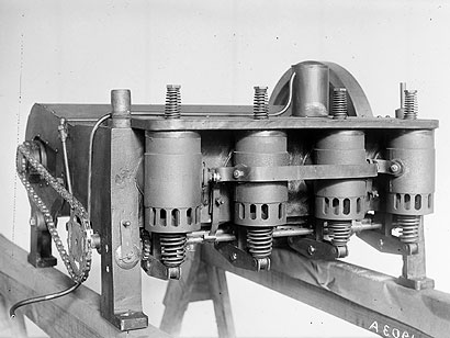
Engine No. 3
Building on Success
Like all their designs, the Wright brothers’ engines evolved in stages. As their abilities as pilots developed and the performance of the Flyers improved, the engine was modified to meet the growing demand for power.
Engine Specifications
- Bore – 4 inches
- Stroke – 4 inches
- Displacement – 201 cubic inches
- Compression ratio – 4.7:1
- Horsepower – 25 hp
- Cooling – Liquid circulated by thermo-siphon and radiator
- Lubrication – Splash system, circulation by pump and gravity
- Dry weight – 180 pounds
Although the Wright brothers shared credit for all their work, their remarkable partnership was built on their often complementary talents. Wilbur often took the lead in aerodynamic theory and design, while Orville contributed many of their elegant mechanical solutions. In engine design, Orville clearly the innovator.
The brothers’ work on the engines began as a joint project, with significant contributions from their talented machinist, Charley Taylor. As the demands for engine performance increased, Orville took on the task of improving their design. Wilbur acknowledged his brothers’ ability, and continued to experiment with Engine No. 3 as Orville pressed ahead, developing the Vertical Four engine in 1906.
Orville’s new engine was the primary powerplant for their aircraft for the next ten years. Although he was the engineer, the true success of the engine lay in the fact that he had a clear understanding of its requirements. It was only a part of the overall aircraft design, which relied on Wilbur’s contributions in other areas
The Wrights’ original engine design came about after their unsuccessful attempt to find an engine manufacturer willing to produce only a few high-performance engines built to their specifications. Working with their machinist Charley Taylor, the Wrights designed and built this four-cylinder engine, which met their most significant specifications: it weighed under 200 pounds, and was capable of delivering at least 8 horsepower.
The 1903 engine performed beyond the Wrights’ expectations, consistently delivering 12 horsepower. Before the famous first flights of December 1903, the engine was thoroughly tested for power output and reliability, each equally important to the Wrights.
Significantly, measuring the propellers’ thrust were the most important engine tests performed before the flights. The Wrights understood that the engine’s power was only as good as the thrust developed by the propellers, that each relied on the other for effective powered flight.
The engine’s ultimate test came with the attempts at powered flight. The engine itself was damaged beyond repair with the rest of the Flyer when the machine was overturned by a gust of wind following the fourth flight. Nevertheless, the successful first flights proved the engine’s ability; in the coming years, the airframe would change dramatically, while the basic form of the engine remained unchanged.
In January of 1904, the Wrights had additional engine blocks cast from the 1903 patterns. The 1904 engine was essentially a duplicate of the 1903 engine. The bore of the cylinders was increased 1/8 of an inch, fuel and oil pumps added, and cooling improved. A compression release mechanism was also installed to stop the engine.
The essential soundness of the design continued to provide sufficient power, which increased through time and modification to 21 horsepower. The engine was kept and reused when the 1904 Flyer was abandoned and the Flyer III was built in 1905.
The flights of 1904 were frustrating for the Wrights. The engine, though not perfect, was the least of their problems. The aircraft’s stability was problematic, and the Wrights moved the engine backward on the airframe in an attempt to change the center of gravity and improve control.
The flights of 1905 were perhaps the most important for the Wrights, as they fully mastered the art of flying. They flew as far as 40 miles, their range limited by the amount of fuel they carried. They made no major modifications to the engine during this time, although the vastly longer flights required significantly more maintenance. The engine’s performance continued to improve, reaching up to 21 horsepower (Hobbs, p.33).
Developed from the engine blocks cast in 1904, Engine No. 3 was destined to remain on the ground. Known as the “guinea pig”, the engine was used fro m1904-1906 as a testing platform (Hobbs, p.32). The improvements to the engine, most notably the auxiliary exhaust ports, increased its performance to 25 horsepower, and pointed the way to a new design. The Wrights tested Engine No. 3 continuously from 1904 to 1906, measuring engine speed and horsepower, and making occasional records in their diaries and notebooks.
Orville designed the Vertical Four engine in 1906 in anticipation of machines capable of carrying more weight and higher performance. The modifications made to Engine No. 3 were the basis for the vertical design. Engines of this kind were used in many Wright aircraft, including the 1908 Model A, the 1909 Military Flyer, and the 1911 Model B.
Founded by Colonel Edward A. Deeds and Charles F. Kettering, the Engineer’s Club of Dayton has proudly celebrated and encouraged the many outstanding engineering professionals from the area since 1914. The mission of The Engineers Club of Dayton is to foster the advancement of business, education, engineering and science, and to promote the professional development of its members. Orville himself was a member, and selected Engine No. 3 as his gift to the club upon his death.
The engine was presented to the club in 1948 by Milton Wright, Orville’s cousin. The engine has been on display since then as an inspiration for its members. An original Wright Vertical Four engine (Serial #43) from the Wright Experience Collection was exhibited in its place during the conservation process. The engine’s preservation to this point is a tribute both to the club’s care of the Wrights’ legacy, as well as Orville’s foresight in placing it in good hands. The club continues to this day, with an active board and hosting a variety of events.
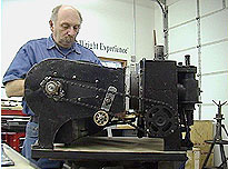
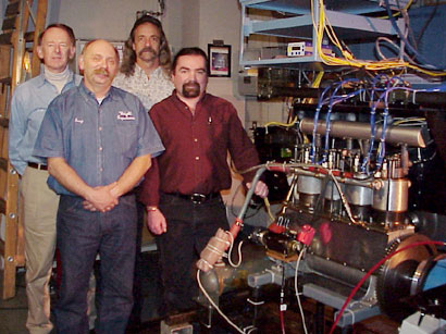
Greg Cone is the Wright Experience’s resident specialist in antique engines. Greg has been restoring both aviation and automotive engines for over 30 years. His work at the Wright Experience is based on exhaustive historical research and painstaking craftsmanship. He previously restored the Wright Vertical Four engine, Serial #20, making it the only original operating Wright engine in the world.
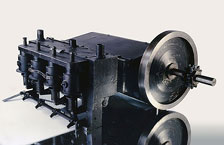
Engine No. 4
Wright Power
The Wright Brothers had a clear concept of the role of engines in their aircraft: to provide reliable, sufficient power. The amount of power was determined as part of the overall design of the aircraft. The Vertical Four engine was the ultimate result of the Wrights’ airplane engine designs.
Engine Specifications
- Bore – 4 3/8 inches
- Stroke – 4 inches
- Displacement – 241 cubic inches
- Compression ratio – 4.7:1
- Horsepower – 35 hp @ 1400 rpm
- Cooling – Liquid circulated by pump and radiator
- Lubrication – Splash system, circulation by pump and gravity
- Dry weight – 180 pounds
The Wrights’ engine was one of the last components designed and built before the successful flights of 1903. After their success in Kitty Hawk, the Wrights built two further horizontal engines for their continuing experiments. One was used on the 1904 and 1905 Flyers, the other, pictured at left, was used as a “guinea pig” for engine development.
The third engine was fitted to a floating platform and tested on the Miami River. The results of these tests led Orville to investigate a new engine design in 1906. The new design was the Vertical Four. As the Wrights’ aircraft improved, so did the requirements of their engines. In each case the Wrights determined ahead of time how much power was required. Although it evolved into a six-cylinder version, the Vertical Four was the final production engine design of the Wrights and powered most of their aircraft through 1912. (Wald, p.42) The Vertical Four was the Wright’s mature engine design, and was the standard powerplant for their most produced airplane, the Model “B”.
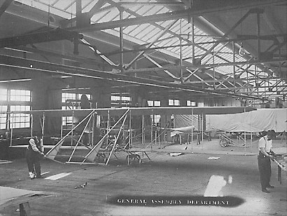
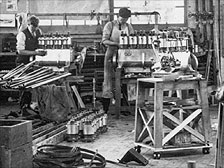
The Wright factory in Dayton, Ohio, was a far cry from the modest bicycle shop where their first engines were made. A fully equipped department produced engines, most of which were used in the Model “B”, the most popular of the Wrights’ designs. Serial numbers as high as 67 have been recorded, and it is possible that the factory produced over 100 engines. The factory was in operation under the Wrights’ ownership from 1910-1915.
The Wright Model “B” was the world’s first production airplane. Designed by the Wrights and put into production in 1910, it was their most popular aircraft. About 125 of these aircraft were manufactured in the US and Europe in the years 1910-1915. Although several new designs followed (up to the Model “K”), there was none as successful as the Model “B”. Each aircraft was fitted with a Wright Vertical Four engine, manufactured in the same factory.
The Wright Exhibition Team existed from 1910-1912. During that time, many of its pilots were killed. The competition from rivals was intense, and the Wrights lost interest in what they called “the mountebank game”. The remaining aircraft of the exhibition team were sold. Frank Coffyn’s machine with Engine #20 was sold to Frederick and Russell Alger of Detroit.
In 1915, the Algers donated their Model “B” with Engine #20 to the University of Michigan Flying Club. The University was a pioneer in aeronautical education, led by Professor Felix Pawlowski. The club eagerly accepted the airplane and planned to fly it at a University regatta at Barton pond in Ann Arbor. Piloted by Michigan student F. E. Loudy, the aircraft crashed almost immediately into the pond. The students were able to rescue the pontoons and the engine, but the aircraft was lost.
F. E. Loudy went on to become the first student in the world to receive an aeronautical engineering degree. The engine was salvaged and placed in storage with the Lincoln Storage Company. Following his crash of the Model “B”, Loudy was responsible for the salvaged engine. (Note his comment that the plane was “wrecked in a storm”). The engine had been in storage at the Lincoln Storage Company, and Loudy made an attempt to convince Orville to pay the bill so the engine could return to the university. No reply from Orville was found.
The letter was found by the Wright Experience while researching the papers of Orville Wright. The team was able to trace the Lincoln Storage Company descendents, who confirmed that the engine was still in storage. Arrangements were made, and the engine was purchased by the Wright Experience in 1999.
An Artifact with a Pulse
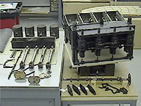
The Wright Experience owns the only operating original Wright Engine in the world- Vertical Four Serial #20. Led by Greg Cone, the Wright Experience began a thorough restoration of the engine including X-rays in 1999. All the parts of the engine are original, except for a piston pin and the spark plugs.
The engine was started for the first time in 85 years in 2000. Since then, the engine has been demonstrated numerous times, including EAA’s AirVenture in both 2000 and 2001. The engine was also run for over six hours in a dynamometer in Rochester, NY, its performance fully measured and documented. Future plans include the engine being installed and used in a brand new, flying Model “B”.
Putting the Engine to the Test
From their first engine of 1903 to the mature engines of the early teens, the Wrights’ engines were carefully designed and tested with specific performance criteria in mind. In January 2001, the Vertical Four engine was run for over 6 hours in a series of dynamometer tests at the Delphi Automotive Systems Technical Center in Rochester, New York. How would the engine perform compared to its performance 91 years earlier?
The Wright Brothers tested each piece of their equipment to make sure it performed as required. In the case of the Vertical Four Engine, the Wrights mounted a flat bladed propeller, which they called a “fan”, on the flywheel. They knew the resistance of this fan from their wind tunnel tests. Knowing this resistance, and using a hand-held revolution counter, they were able to calculate the horsepower of the engine.
The Wright Experience reproduced this test, following written descriptions of the Wrights’ original test. On the second run of the engine, the fan screwed itself to the flywheel and split. Fearing they had made a serious misjudgement, the team review Orville’s notes on the test. At the bottom, they found this entry: “Second run, 600 rpm, fan split”. The Wrights had the same problem! The solution used by the Wright Experience is the same one employed by the Wrights: a two-bladed flat fan with a steel hub.
The performance would be based on measurements taken while the engine was running under simulated flight conditions. The test setup would need to capture a full suite of performance data. Testing occurred at Delphi Automotive Systems technical center in Rochester, NY from February 19 – 23. The engine was installed in an engine test cell and coupled to a DC electric dynamometer.
An exhaust header was installed to collect the exhaust gases from the open ports and house the required thermocouples, emissions sampling, and air-fuel ratio sensors. The engine was also outfitted with combustion analysis equipment to monitor in-cylinder pressures and calculate mean effective pressure values and combustion stability.
Other measurements that were taken during the tests were airflow and fuel flow, engine brake torque, and standard engine temperatures and pressures.
Since the engine is 91 years old, a limited test program was planned that would obtain important data while minimizing the run time. Numerous test runs were made, varying both the test equipment and fuel. Exxon-Mobil generously produced a vintage fuel, called ’65 test’, which was used as well as modern 80-octane aviation fuel.
Other variations included two different size fuel flow nozzles, the degree of ignition spark timing, and the emissions header both installed and removed. The engine was run from idling speed to full power. By carefully controlling the test parameters, the team was able to measure a full range of performance.
In a letter dated April 12, 1911, Orville stated that “We look upon reliability in running as of much more importance than lightness of weight in aeroplane motors.” Did the results support this statement? What were the results? How was the Wrights’ preference for reliability demonstrated in the engine’s performance?
The test results showed low volumetric efficiency; variability in the charge from cylinder to cylinder due to suction intake valves; low thermal efficiency; variability in air/fuel ratio from cylinder to cylinder(typically rich); and high fuel consumption (about double modern engines).
However, the rich air/fuel ratio, suction activated valves, auxiliary ports and low operating speed of this engine all contributed to enhanced reliability by lowering the cylinder head temperatures. Problems associated with high head temperatures included valve failures and detonation, which were common in engines of this period. By intentionally detuning the engine, a significant gain in longevity was achieved.
Combined with their highly efficient propellers, the engine provided sufficient reliable power for the mature Wright aircraft.
Production of Vertical Four engines ended in 1915. The Wright Company eventually became reorganized as the Wright Aeronautical Company and was one of the most respected producers of aircraft engines in the country. Although engine technology developed far beyond the Wrights’ innovations, the precision of their engineering and engine design remains one of their most lasting, if least well known, achievements.
Vertical Four Serial #20 will fly again. The Wright Experience is currently building a new model “B”, whose power plant will be Vertical Four Serial #20. The performance of the engine in the dynamometer tests proves its reliability. The engine is also serving as a model for new production engines, as well as for the restoration of three other original Vertical Four Engines.
Since Wright engines were manufactured in significant numbers in the US and Europe, there are still a number of original Wright engines in collections around the world. The Horizontal engines are in the collections of the Air and Space Museum (1903 Flyer), Carillon Park (1905 Flyer III), and the Engineer’s Club of Dayton (engine #3).
The National Air and Space Museum has four vertical engines: the 1909 Military Flyer engine (vertical four), the Vin Fiz Engine (vertical four), and two Wright six-cylinder vertical engines. Other Wright engines are in the collection of the Air Force Museum, the Franklin Institute, and the Musee de l’Air, the Connecticut Aviation Historical Society, the Scottish Museum, the Museum of Science and Industry, Chicago.
Vertical Four #20 remains the only operating original Wright engine in the world.