
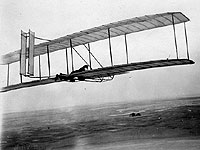
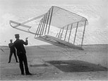
Modified after its disappointing first trials with the addition of a third spar and trussed ribs, this glider airplane gave Wilbur Wright glides of more than 300 feet.
- Wingspan: 22 ft
- Chord: 7 ft
- Weight: 98 lbs
- Longest Recorded Glide: 366 ft
- Longest Recorded Time in the Air: 10-20 sec
- Number of Successful Flights: Less than 100 (Exact Number Unknown)
The goal of the Wright Experience is to fully understand the Wrights’ scientific process and achievement. In building as accurate a reproduction as possible and conducting its own tests, the team hopes to gather new insights into the performance of the machine and the genius of the Wrights.
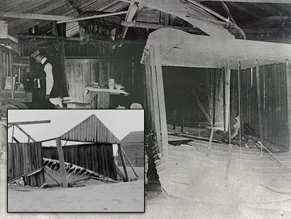
After the encouraging results of their 1900 glider tests, the Wrights returned to Kitty Hawk in 1901 with the largest glider ever built. Hopeful of its performance, they were unaware that the glider tests would lead them to secrets of flight then still unknown. The isolation of the Outer Banks offered the Wrights an ideal location for their experiments. The Wrights made detailed measurements of the wind speeds and heights of sand dunes, information critical to their experiments.
In 1901, the Wright brothers had built and tested a glider whose flights were a source of great disappointment and frustration. They based their design on the lift tables of Otto Lilienthal, but the performance of the glider was far below what they had predicted.
In order to fly, the glider required a greater wind speed and a higher angle of attack than they had anticipated, and required a significant modification to the airfoil in order to get even marginally satisfactory results. Although the glider’s performance impressed their colleague Octave Chanute, these unexpected results led them to question the accuracy of Lilienthal’s data.
No original plans exist for the 1901 glider. In order to build an accurate glider, the team must trust the information in diaries, letters, lectures, and photographs taken by the brothers.
The record left behind by the Wrights about their machines is incomplete. It requires meticulous research in order to find the clues that can often make an enormous difference in both the authenticity and the performance of the machine. The greatest challenge lies in staying faithful to the Wrights’ work: it is a matter of trust.
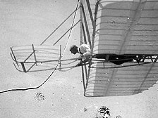
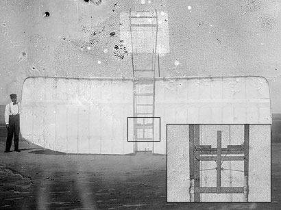
Detailed scrutiny of the photographic record yields many important details, such as the wing warping mechanism pictured above. There is no detailed description by the Wrights of this device. The photographs themselves are the only physical evidence of the machines’ existence.
The wings of the 1901 glider had a total surface area of 308 feet, with a span of 22 feet and a chord of 7 feet. Although large, the wings seem stubby in their proportions. The profile of the wing was a curve with a depth of 1 in 12, which was taken from Otto Lilienthal’s published test results, and was much deeper than the year before. A spar in the bottom wing was used to secure small upright posts, which were used to truss down the deep curve of the wing when the Wrights discovered control problems in their initial glides.
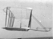
The front of the 1901 glider is pointed up at a steep angle, yet it flies very low. The glider required a much steeper angle and stronger winds to lift than the Wrights originally predicted. In 1901, pitch as one of two aspects of control identified by the Wrights. On the 1901 glider, pitch was controlled by means of the forward rudder, or canard. The leading edge (front end) was unmovable. Two sticks attached to the trailing edge and a horizontal bar across the skids were used to move the trailing edge (rear end) up and down, warping the back half of the surface for positive or negative lift.
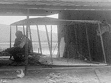
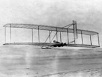
The second aspect of control for the Wrights in 1901 was lateral motion. The wing warping system was first employed on their 1899 kite and adapted for use on the 1901 machine. As the operator lay prone in the slot cut out of the bottom wing, his feet rested on the T-shaped bar at the rear. When activated, the mechanism twisted the entire surface of the wings. The twisting wings gave greater lift to one side over the other, with the idea that there would be a banking turn. When put into practice, the Wrights discovered much to their dismay that although the turn started in the intended direction, the machine soon reversed itself and began a skidding turn in the opposite direction. This phenomena, called “well-digging” by the Wrights, was actually their first hint that a third, as yet undiscovered axis of control was required for controlled flight, known today as yaw.
As Wilbur stated in a 1901 article, “All who are concerned with aerial navigation agree that the safety of the operator is more important to successful experimentation than any other point.” Another way the Wrights were unique in their designs was the horizontal or prone position of the pilot. Despite the concerns of their family and colleagues, they were convinced it was a viable and aerodynamically sound position for the operation of the machine:
“The horizontal position requires assistance for the launching, but once the machine is in the air, it travels more steadily and its turning motions are slower, the operator’s body now being a part of the machine, and its inertia accordingly greater… Landings are less difficult and less dangerous than one might naturally suppose… On soft sand or turf it is in any case less dangerous—if indeed there is any risk—than to try and land on one’s feet.”
There was, of course, some solid science behind the position as well:
“The fact that the head resistance of a flying machine is reduced by a good third if the operator adopts the horizontal position is a further argument of great consequence to the practicability of this scheme.”
The 1901 glider went through significant design changes as a result of its initial flight tests. Working from a fundamentally sound design, the Wrights were able to isolate problems in their design and alter it accordingly. The reproduction glider follows the modifications.
The design of the 1901 machine sought to be an improvement of the 1900 glider, and was similarly based on the lift data compiled by Otto Lilienthal. In Wilbur’s words:
“Accordingly, the curvature of the surface was increased to 1 in 12, to conform to the shape on which Lilienthal’s table was based, and to be on the safe side, we also decided to increase the area of the machine from 165 square feet to 308 square feet, although so large a machine had never been deemed controllable.”
In describing the machine’s first trials, Wilbur relates their surprise:
“The machine sailed off and made an undulating flight of a little more than 300 feet. To the onlookers this flight seemed very successful, but to the operator it was known that the full power of the rudder had been required to keep the machine from either running into the ground or rising so high as to lose all headway. In the 1900 machine one fourth as much rudder action had been sufficient to give much better control. It was apparent that something was radically wrong, though we were for some time unable to locate the trouble.”
When the brothers deduced that the movement of the center of pressure across the surface of the wings resulted in this imbalance and difficulty of control, a modification to the wing shape was required:
“This point having been definitely settled, we proceeded to truss down the ribs of the whole machine, so as to reduce the depth of curvature… On resuming gliding, we found that the old conditions of the preceding year had returned; and after a few trials, made a glide of 366 feet and soon after one of 389 feet.” (McFarland, pp. 107-111)
The Wright’s clarity of purpose is well illustrated in the above passages. When faced with a puzzling and unforeseen problem with their design, they were able to isolate the source of difficulty and correct the problem.
The 1901 glider was the last machine the Wrights built based on the theories and data of other researchers. Studying its anatomy in terms of function reveals the Wrights as well ahead of their contemporaries and on the threshold of innovation.
The Wrights returned to Dayton after the 1901 gliding season disappointed in their work. Their questions led to a systematic evaluation of the flights and a series of wind tunnel tests to develop their ideas. The result was the birth of modern aeronautical engineering.
The wind tunnel tests of 2001 are important for several reasons: they confirm the performance of the glider as reported by the Wrights in 1901, and extend our understanding of the Wrights’ work at what proved to be a critical time in the development of aviation. As stated by Dr. Kochersberger:
“The 1901 glider was critical in providing the Wrights many important observations needed to solve the overall problem of powered flight, and in many ways, 2002 is the 100th anniversary of the beginning of the systematic approach to aeronautical engineering.”
The effectiveness of these tests and of similar evaluations of reproduction Wright propellers and an original Wright engine demonstrates the value in maintaining fidelity to the Wrights’ original designs. The reproduction glider is currently on display at the College Park Aviation Museum in College Park, Maryland.
The Wrights’ analysis of their flights left them convinced that the Lilienthal lift tables they had trusted were in error. They proceeded to devise a series of instruments to test the accuracy of the data, each of which was designed to measure the lifting ability of a curved surface against a flat plate placed in a stream of moving air.
The evolution of these devices resulted in the first use of a wind tunnel for aerodynamic research and design. The hundreds of tests carried out by the Wrights not only led them to their revolutionary glider of 1902, but established the fundamental practices of wind tunnel testing which has been in aerodynamic engineering ever since.
Experiments
Kite Tests: The practice of “kiting” their machines began in 1900 and was integral to the Wrights’ experiments of 1901. Kite tests alternated with flight tests as observations and modifications were made to the machine. Measurements typically included those for lift, drag, angle of attack, wind speed, and the slope of the ground. The 1901 kite tests were particularly helpful in identifying the control problems associated with the movement of the center of pressure.
Flight Tests: The flight tests of 1901 started as soon as the machine was ready. It appears that Wilbur did all the flying. Several glides were carefully recorded as with the kite tests. Flight duration, speed, altitude, and distance were all measured, as well as wind speed and slope of the ground covered. The 1901 flight tests exposed two significant, unforeseen problems of the 1901 glider: insufficient lift and lack of lateral control.
Analysis: In the months following the 1901 tests, the Wrights reviewed the results of their experiments, trying to understand why the machine performed as it did, and how they might resolve its design flaws. Much of the analysis was preserved in Wilbur’s correspondence with Octave Chanute, who was present for some of the 1901 tests. Eventually, the calculations about the glider’s performance were only partially trusted by the Wrights, who found that despite their best efforts, too much data had been estimated and therefore the results would have too great a margin of error to be of much value.
Test Design: The 2001 wind tunnel tests and analysis of the 1901 Glider reproduction were carried out by Old Dominion University in cooperation with the Wright Experience and with support from NASA. The full-scale tunnel at Langley Air Force Base in Hampton, VA affords an opportunity to test the reproduction machine directly under controlled conditions.
The test was designed and run by Dr. Kevin Kochersberger, on sabbatical from the Rochester Institute of Technology. All the descriptions of the test that follow are excerpts from his paper, “An Evaluation of the Wright 1901 Glider Using Full Scale Wind Tunnel Data” (AIAA, 2002).
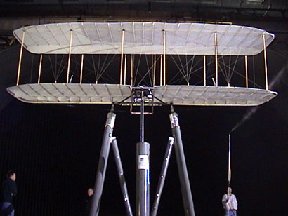
The 1901 glider was mounted to a three-post support system, which allows for the glider to be moved to specific angles of attack. The entire assembly is mounted to a turntable for measurements at different angles of yaw. The supports also transfer the loads of the glider to balances located below the testing platform. The balances then drive scales whose measurements are transferred via computer to the control room, where data is recorded.
Test Runs: Thirty-six test runs were performed in November 2001, divided between longitudinal and lateral configurations. The glider was tested at a range of angles of attack (from -2° to +20°), sideslip angles (±15°), and canard and warp deflections that covered the operating range of the machine. Speeds between 20 and 33 mph were used to simulate the range of operating speeds as reported by Wilbur Wright in his 1901 lecture to the Western Society of Engineer.
Analysis: The longitude tests showed the glider to have an optimal lift-to-drag ratio of 4.5 measured at a trim flight speed of 28 mph. The Wrights consistently recorded glide and kited lift-to-drag ratios of about 6. This higher figure may be accounted for by including, among other factors, ground effect, updrafts, the Wrights’ slingshot launching technique, and variability in the wing covering.
The lateral tests showed that the machine cannot hold a steady roll rate, and has only slight yaw stability due to the lack of vertically oriented surfaces. A simulation of a right turn shows adverse yaw steering the glider to the left–the opposite direction intended.
Additionally, tests not in the original plan were made by modifying the fabric wing covering to simulate a tighter, less porous covering which may have been a condition during flights in drizzling rain conditions. In a dynamic simulation performed using Simulink™ the machine became less stable, and would require significant input from the pilot to make corrections to the flight path with the canard and by moving forward or backward to shift the center of gravity. This is indeed similar to the experiences recorded by the Wrights.
At The Wright Experience, we created a reproduction glider, which was built with the Wrights’ modifications and wind-tunnel tested in 2001. It is on display at the College Park (MD) Aviation Museum.