Although the Wrights’ were the first to use a wind tunnel as part of the aircraft design process, they did not invent it, or the notion of testing surfaces in a laboratory environment.
Benjamin Robins (1707-1751) – Robins was the first scientist to measure drag with an instrument, spinning shapes of different surfaces on a ‘whirling arm’ apparatus. This was the first known use of the whirling arm, which was the predecessor of the wind tunnel. Whirling arms were used extensively in the 19th century by experimenters including the Wrights’ main predecessors and competitors, Sir George Cayley, Otto Lilienthal, Hiram Maxim, and Samuel Pierpont Langley.
Frank H. Wenham (1824-1908) – Disappointed with his work with whirling arms, Wenham designed and built the first wind tunnel in 1871. He described it as “a trunk 12 feet long and 18 inches square, to direct the current horizontally, and in parallel course.” Wenham tested a variety of surfaces in his tunnel, measuring lift-to-drag ratios and testing the effect of different aspect ratios.
Albert Zahm – In 1901, Albert Zahm of Catholic University, Washington, DC, built a wind tunnel financed by a wealthy sponsor, Hugo Mattullah. It operated from 1901-1908, and despite successful and sophisticated tests, the tunnel was eventually shut down. Zahm became an adversary of the Wrights in their legal battles.
The Wrights’ wind tunnel was created to test the work of their predecessor, Otto Lilienthal. His scientific approach to flight was the basis for the Wrights’ early designs. By the fall of 1901, they had developed doubts about his pioneering data. With the tunnel, they took a bold step forward.
Following their disappointing 1901 gliding season, the Wrights questioned the basis for their designs: the mathematical tables of lifting performance compiled by Otto Lilienthal. Their gliders simply did not perform as the tables predicted. Had the great German pioneer made an error?
Like their aircraft and engines, the Wrights’ 1901 wind tunnel was developed in stages, through a series of variations and experiments. The challenge of creating reproductions of these pioneering instruments is that they exist only in descriptions – the Wrights did not preserve them.
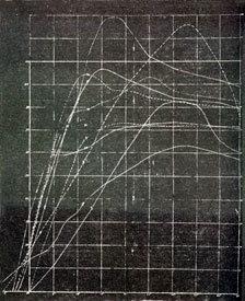
Bicycle Experiment: The Wrights’ cycles were their first airfoil testing platform. A bicycle wheel was mounted horizontally over the front wheel and attached to the handlebars. Two vertical surfaces were mounted to the horizontal wheel: one a model airfoil, the other a flat plate. According to Lilienthal, if the flat plate was set at 90° to the wind, the lift of the airfoil, if set at 5°, would balance the drag. It did not. It balanced at 24° – nearly fives time what Lilienthal had predicted.
Although this apparatus was crude, the test proved that the basis for Lilienthal’s tables was flawed. The problem with the bicycle setup was that it was impossible to get a perfect airflow over the surfaces while riding the bike up and down the streets. A more stable, controlled environment was needed, and the Wrights built their first wind tunnel.
Tunnel Development: The fate of the original tunnel is unknown. Fortunately, there was nothing really special about it. Surprisingly, this was part of its design. Following the bicycle experiments, Orville built their first wind tunnel, attaching a fan to an 18-inch starch box. A smaller version of the bicycle device for balancing surfaces was installed, with a window in the top of the box to view the results. Although this tunnel was used for only one day, it again showed that Lilienthal’s data was flawed – the flat plate and the airfoil did not balance as he had predicted (Jakab, p. 124).
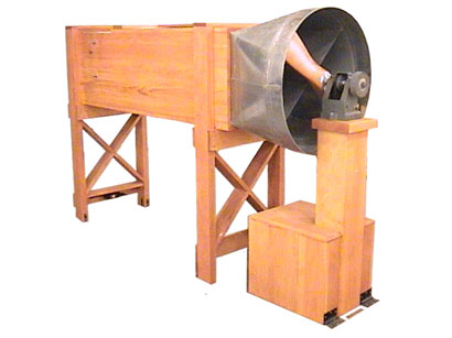
The final tunnel was built in October of 1901. At six feet long, and 16 inches square, it was a significant improvement from the starch box. The Wrights conducted the remainder of their tests in this tunnel, and abandoned it when the tests were complete. This reproduction was built from Orville’s letters, sketches, and notes. It is unique in the Wrights’ machines in that its aerodynamic qualities are easily reproduced – it was only a simple wooden box.
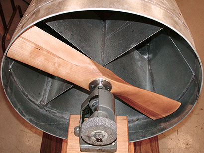
The Fan: A lost component of the tunnel, this reproduction actually benefits from the Wrights’ work. The fan was an early form of propeller, used originally to circulate air in the bicycle shop. Like the original tunnel, it no longer exists. The wind it created, however, is well recorded. The Wrights spent nearly a month trying to tame the swirling air currents it produced. Eventually, a lattice and a screen were placed in front of the fan to straighten the airflow before it reached the balances.
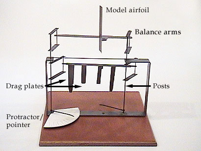
The Airfoils: The critical models for the experiments. The Wrights tested over 200 model airfoils in their wind tunnel before settling on a final testing program of 48. The airfoils were mostly made of sheet steel, cut, bent, and hammered into shape. Some were modified with solder and wax. There was a great variety of shapes: squares, rectangles, ellipses, and more. Biplane and triplane configurations were tested, all in an effort to understand the dynamic characteristics of different wings. Although many were 4″ square, the same area as the drag plates of the lift balance, some were larger. It is not known how the Wrights compensated for this difference.
Using high school math, hacksaw blades and bicycle spokes, the Wrights reduced the elements of flight to two fragile balances, the essential instruments used in their wind tunnel experiments. In 1901, the L=CLkSV2 formula was the accepted equation for calculating the lift of a wing. Though neither had completed high school, each of the Wrights had an excellent working ability in algebra and trigonometry. It was all they needed to find the error in Lilienthal’s tables.
The Wrights tested model wings in their wind tunnel using two balances, one for lift, one for drag, or “drift” in their terms. Each converted the performance of the wing into mechanical action. The resulting change in the geometry of the balance gave them a measurable result to record and interpret.
The Lift Balance: The lift balance has two sets of arms, each holding test surfaces. The upper arms hold the model airfoils, suspended on a horizontal vane. The lower arms have four finger-like drag plates attached to another horizontal vane. All the arms are connected by vertical posts. The arms rotate when the airfoil is placed in the airflow, and then the upper and lower arms can be adjusted independently, and an angle is indicated on the pointer.
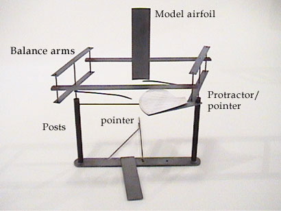
The Wright Lift balance is a device which resolves two opposing forces, lift and drag. These forces act on the balance by turning the arms of the balance around fixed points. This was called “twisting action” by Wilbur. When the forces come to a point of equilibrium, the geometry of the balance allows the proportion of the airfoil lift and the drag of the plates to be expressed by a single angle. This proportion is a critical element in the equation for determining the lift of a wing.
The Drift Balance: The drift balance has two sets of arms, but only one holds a test surface. The lift and drag from the airfoil rotate the arms, indicating an angle on the pointer. The drift balance also differs from the lift balance in that the entire balance is rotated to different angles of attack, indicated by degrees marked on the floor of the tunnel.
The Wright drift balance is a device which allows the lift and drag of an airfoil to come to balance in a controlled setting. These forces act on the balance by turning the arms of the balance around fixed points. The geometry of the balance allows the ratio of lift to drag of the wing to be measured by a single angle. This proportion is critical in determining the performance of a wing.
The Wright brothers’ wind tunnel experiments profoundly affected their understanding of flight, and set them far ahead of any of their competitors. Ironically, the wing they used on their next glider was one never tested in the tunnel.
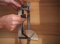
Bill Hadden of the Wright Experience built the reproduction balances after making detailed measurements of the copies in the collection of the National Air and Space Museum. His experience with the balances makes them look easy to operate, but don’t be fooled. It takes patience and care to keep the delicate connections from collapsing.
The Wright’s work is still being tested in the wind tunnel. With the support and collaboration of NASA , the Discovery of Flight Foundation, Wichita State University and Old Dominion University, the Wright Experience has been conducting wind tunnel tests of full scale reproduction Wright propellers, airfoils, and gliders. The Langley tunnel (now operated by Old Dominion University at Langley Air Force Base in Hampton, Virginia once hosted a meeting attended by Orville Wright himself. The new tests allow researchers to test the performance of reproduction machines, gaining new insights into the achievement of the Wrights.